

Troubleshooting Methods for Resolver Feedback Anomalies in Vacuum Servo Motors
Problem Description
When the servo motor is correctly wired, it fails to rotate and shows no feedback in the Servotronix software.
Keywords
Servo motor; resolver; feedback; encoder alarm; position loss; resolver signal loss
Cause Analysis
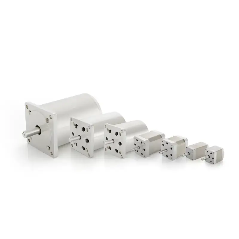
A resolver is an electromagnetic sensor used to measure the angular displacement and angular velocity of a rotating object. It consists of a stator and a rotor; typically, the rotor is fixed to the motor shaft and rotates with it.
The stator winding of the resolver serves as the primary side of a transformer and receives the excitation voltage. The rotor winding acts as the secondary side, generating an induced voltage through electrical resonance and magnetic coupling. The amplitude of the output voltage from the rotor winding varies as a sine or cosine function of the rotor angle. By converting the output signal via an analog-to-digital converter and calculating the arctangent value, the current angular displacement of the rotor can be obtained; differentiating the angular displacement with respect to time gives the rotational speed.
During commissioning, place the motor on a table or avoid locking it onto the load. Observe the encoder position in the drive software interface while manually rotating the motor shaft. When rotating one full turn forward and one full turn backward, the encoder position in the software interface should increase by 65,536 and decrease by 65,536, respectively (some drives use 4,096 or 16,384 depending on decoding resolution).
If the encoder position in the software interface remains static or changes irregularly, wiring errors should be considered. Two possibilities are as follows:
- Incorrect Resolver Wiring
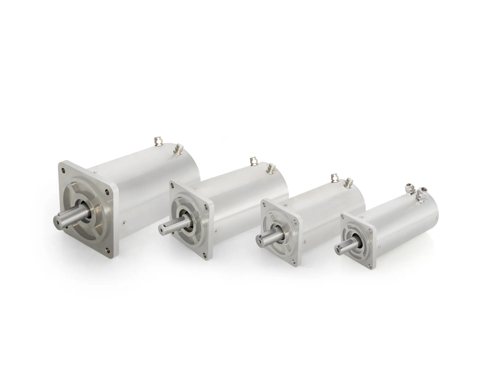
The resolver requires six wires: Sine+, Sine-, Cosine+, Cosine-, Reference+, and Reference-. When using a connector for feedthrough, if the soldering sequence does not match our specified pinout, feedback information will be lost, and the motor will not rotate. For applications involving vacuum high-low temperature servo motors, high-temperature Vacuum Servo Motors, low-temperature vacuum servo motors, deep cryogenic vacuum servo motors, or ultra-high-temperature vacuum servo motors, ensuring correct resolver wiring is especially critical, as these extreme environments leave no margin for signal errors.
- Resolver Wires Not Properly Connected
During soldering, poor connections may result in loose or intermittent contact. Alternatively, the resolver wires may break during motor operation—for example, due to high temperature exposure.
Solutions
- First, unscrew the connector and inspect whether any wires are broken. If a broken wire is found, resolder it. The problem is then resolved.
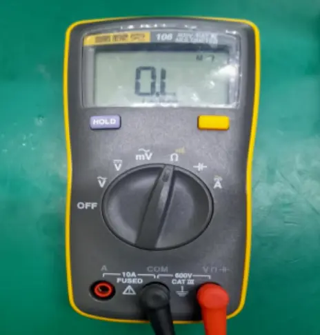
- If no broken wires are found, use a multimeter.
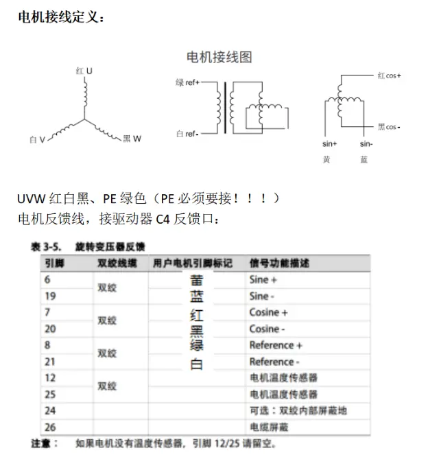
As shown in the diagram:
The resolver signal pinout used by our company is as follows:
- Yellow/Blue pair: sin
- Red/Black pair: cos
- Green/White pair: ref
Set the multimeter to ohms mode and perform the following measurements:
- Measure the red/black pair: the resistance should be approximately 60 Ω.
- Measure the green/white pair: the resistance should be approximately 30 Ω.
- Measure the yellow/blue pair: the resistance should be approximately 60 Ω.
If the measured values deviate, the wiring is incorrect. Rewire according to our specified pinout.
It is recommended to take measurements from the drive terminal side to thoroughly verify the wiring integrity.
When working with specialized motors such as cleanroom vacuum servo motors, high vacuum precision servo motors, low outgassing vacuum servo motors, semiconductor cleanroom servo motors, extreme temperature resistant servo motors, Class 1000 cleanroom vacuum servo motors, Class 100 cleanroom vacuum servo motors, oil-free vacuum servo motors, ultra-high vacuum (UHV) servo motors, or particle contamination prevention vacuum servo motors, careful verification of resolver wiring and shielding is essential to maintain reliable feedback and positioning accuracy.