


Here’s the English translation of your soft article, with the target keywords seamlessly integrated so they read naturally within the technical context
Do You Need a Resistor for Pulse/Direction Terminals? Kingsni Technology Teaches You the Right Wiring
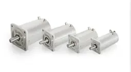
When wiring a Stepper Motor drive, a common question for many engineers is whether a series resistor is needed for the pulse (PUL) and direction (DIR) signal terminals. Incorrect wiring can cause signal abnormalities, prevent the motor from running, or even damage the internal optocoupler of the drive. Based on years of drive application experience, Kingsni Technology provides a clear answer.
The Key Criterion: Voltage Supported by the Drive’s Terminals
Whether an external resistor is required depends entirely on whether the voltage supported by the drive’s pulse/direction terminals matches the actual control signal voltage.
Case 1: Drive terminals support 24V and you’re using a 24V supply
If your stepper drive has pulse/direction terminals designed to support 24V, and you are using a 24V switching power supply to provide the drive voltage, then no external resistor is needed– you can connect directly. The signal level is compatible, and the internal circuit already has current‑limiting capability.
Case 2: Drive terminals support only 5V but you’re using a 24V supply
If your stepper drive has pulse/direction terminals that only support 5V (common in older or low‑voltage drives), and your control signal is from a 24V switching power supply, then you must add an external resistor to limit current – otherwise the internal optocoupler will burn out. Industry practice typically calls for a 2kΩ (2000 ohm) resistor in series to step the 24V down to about 5V that the drive can accept.
> Note: Always check the drive manual for the exact value, but between 1.8kΩ and 2.2kΩ is typical. A 2kΩ resistor is a safe, universal choice.
Wiring Tips
- If you are unsure about the voltage rating of your drive’s terminals, consult the product documentation or contact the manufacturer.
- An external resistor should be placed in series with the pulse/direction signal line, close to the drive side.
- For common‑anode wiring, the resistor can be added to the common anode line or to each signal line.
Kingsni Technology – Making Drive Wiring Simpler
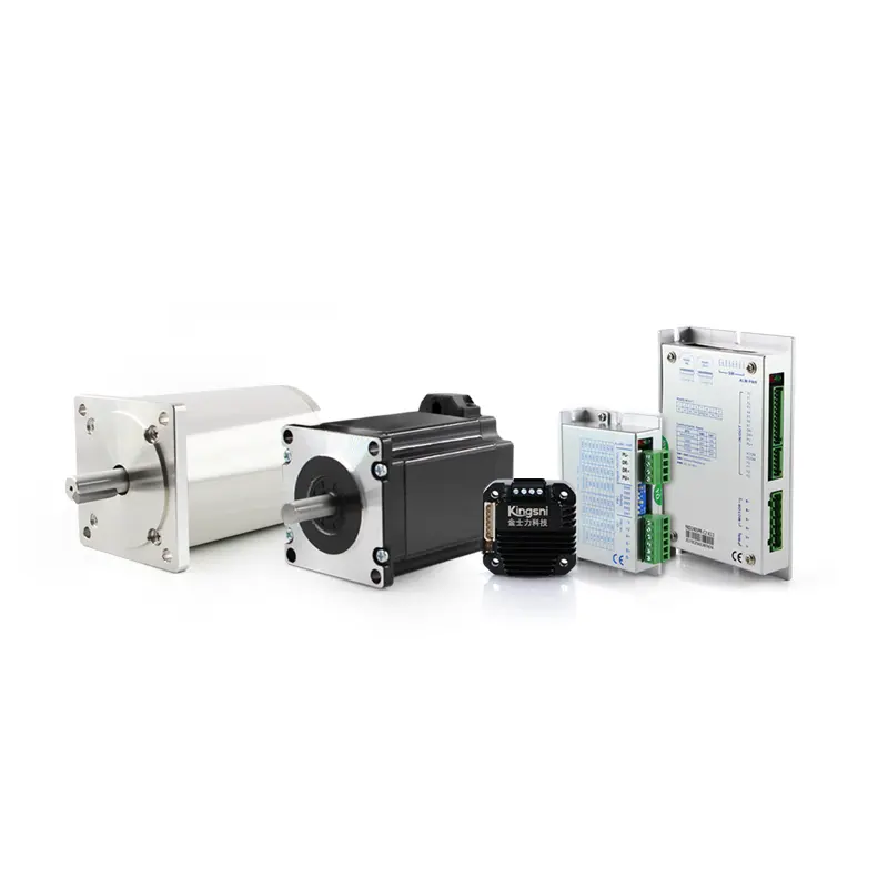
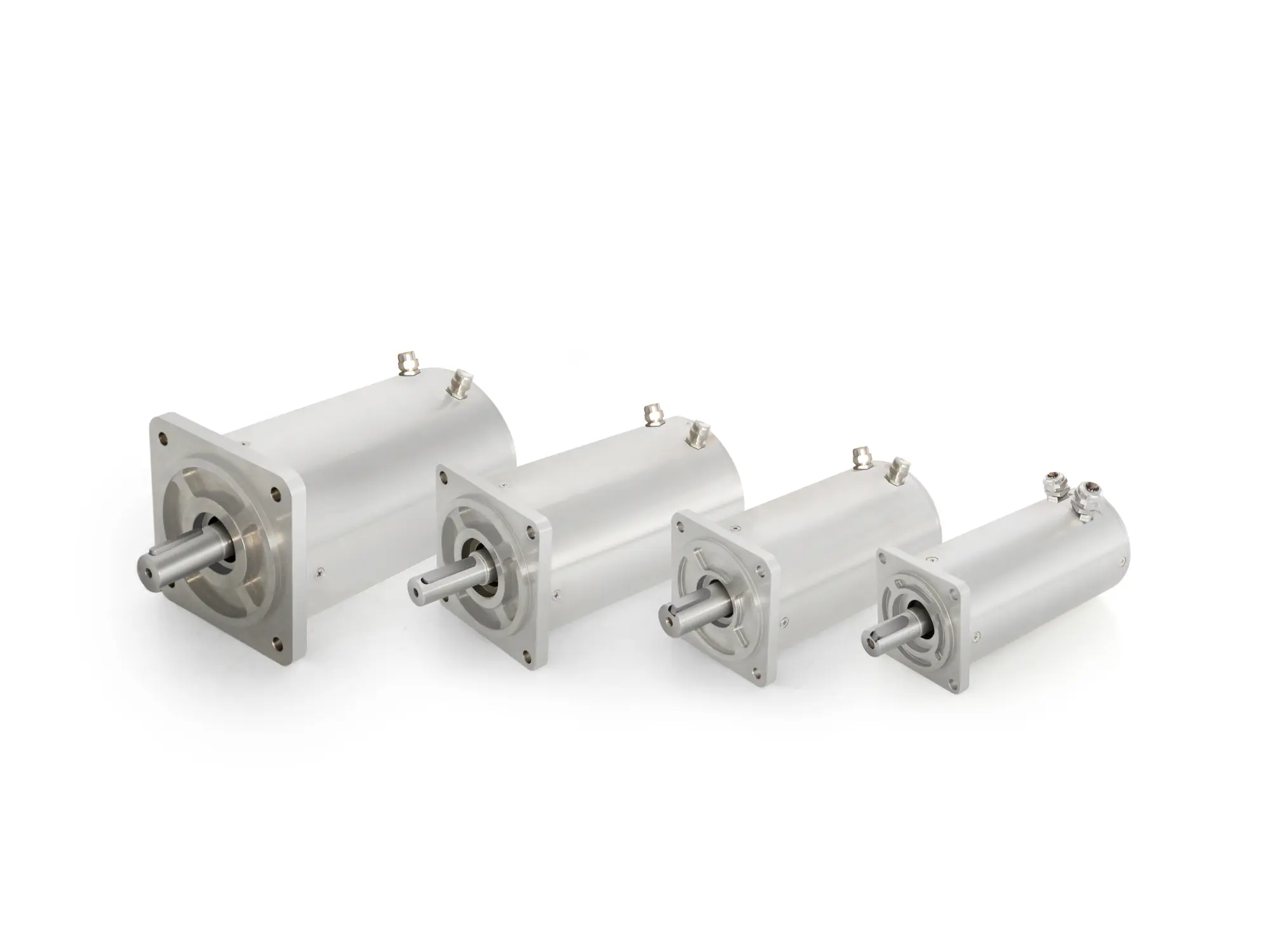
As a professional brand in extreme‑environment motion control, Kingsni Technology (Kingsni) designs its stepper drives with user convenience in mind. Our KSD Series Stepper Drives feature pulse/direction terminals that support 5V~24V wide‑voltage input with built‑in current‑limiting circuitry – no manual external resistors are needed, and they are compatible with most PLCs and controllers, greatly simplifying wiring.
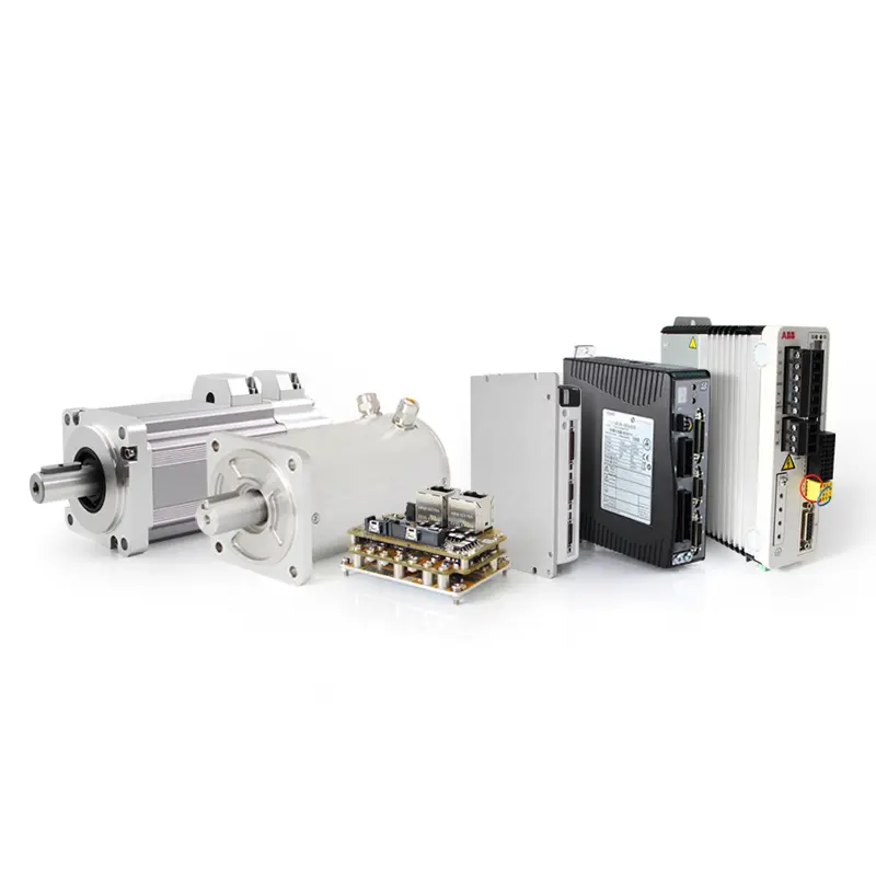
In addition, Kingsni drives are trusted across a wide range of challenging applications – from vacuum stepper motors and in‑vacuum stepper motors to low temperature stepper motors, cryogenic stepper motors, high temperature stepper motors, ultra high temperature stepper motors, radiation resistant stepper motors, radiation hardened stepper motors, as well as high/low temperature servo motors and high/low temperature stepper motors. They are also well suited for use with standard motors in ordinary automation.
Key advantages of Kingsni drives:
- Operating temperature: -40°C to +70°C, for harsh environments
- Microstep resolution up to 25,600, ultra‑smooth operation
- Supports pulse/direction, RS485, EtherCAT, and CANopen
- Suitable for vacuum, high/low temperature, radiation, and other special scenarios
Choose Kingsni for simpler wiring and more reliable stepper systems.
Kingsni Technology – Precision Drive, Smart Control for the Future