


Hot Products
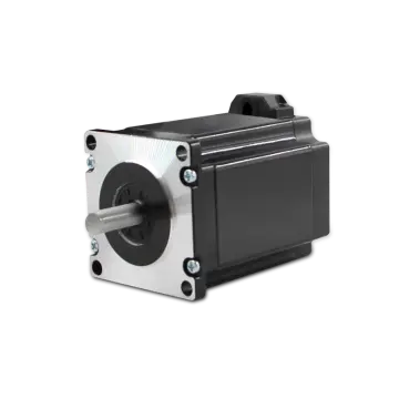
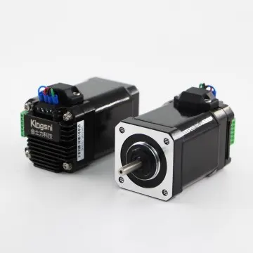
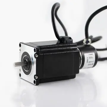


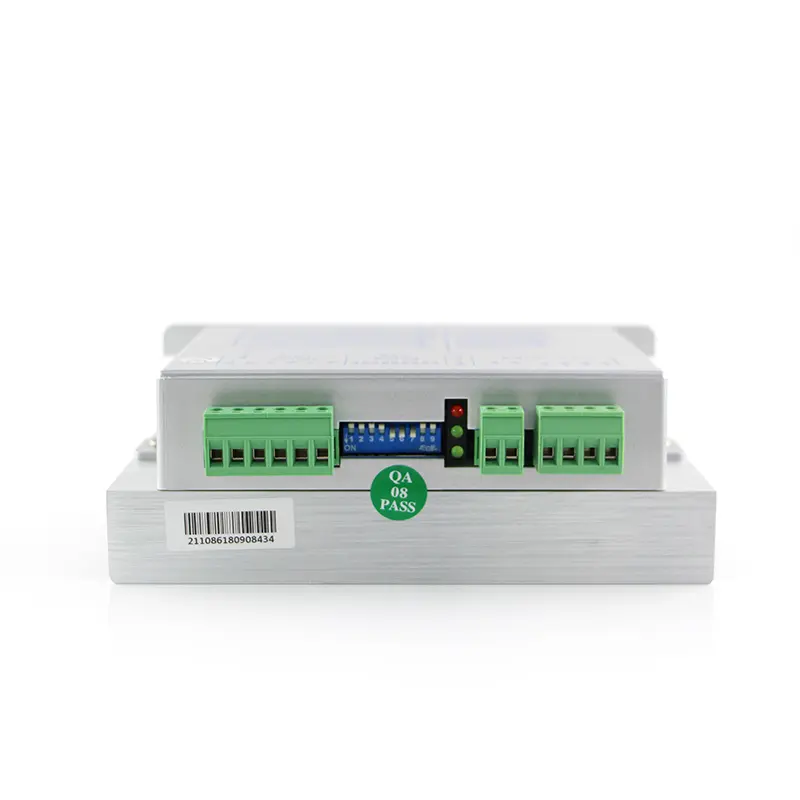
High-Precision YKE2204M Stepper Drive from China Suppliers - Reliable Factory Solutions for Medical & Industrial Applications
Stepper Drive Settings & Specifications
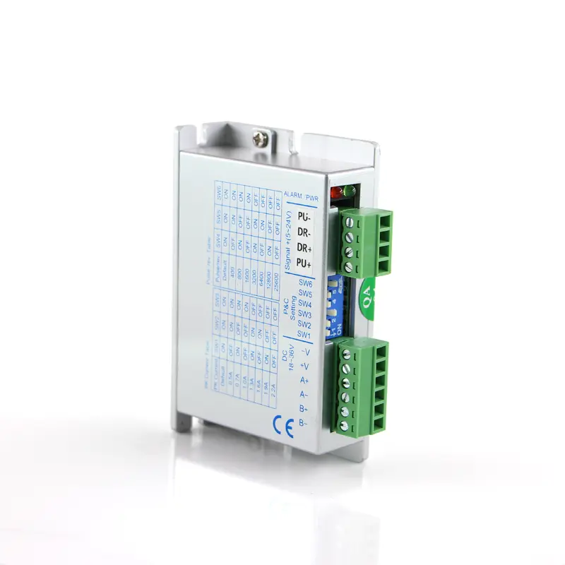
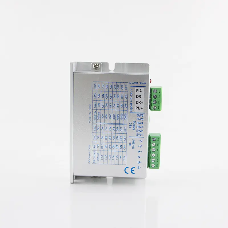
YKE2204M Microstep Setting
| Microstep | 1 | 8 | 16 | 32 |
|---|---|---|---|---|
| PU/Rev | Default (200) | 1600 | 3200 | 6400 |
| SW6 | ON | ON | OFF | OFF |
| SW5 | ON | OFF | ON | OFF |
SW4 Configuration: OFF = Half Current | ON = Full Current
YKE2204M Current Setting
| Current RMS | Default (0.2) | 0.4 | 0.5 | 0.7 | 0.9 | 1.1 | 1.4 | 1.6 |
|---|---|---|---|---|---|---|---|---|
| Current Peak | Default (0.3) | 0.5 | 0.7 | 1.0 | 1.3 | 1.6 | 1.9 | 2.2 |
| SW3 | ON | ON | ON | ON | OFF | OFF | OFF | OFF |
| SW2 | ON | ON | OFF | OFF | ON | ON | OFF | OFF |
| SW1 | ON | OFF | ON | OFF | ON | OFF | ON | OFF |
Terminal Introduction
| Symbol | Function | Specification |
|---|---|---|
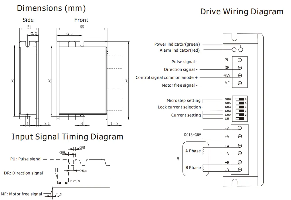
| PWR | Power indicator | When power on, the green indicator lights up. |
| ALARM | Fault indicator | When over current, under voltage or over voltage, the red indicator lights up. |
| PU | Pulse signal photoelectric isolation - |
Effects on falling edge, the motor moves a step when the pulse goes from high to low. Built-in input resistance 384Ω, requirements: low level 0-0.5V, high level is the same as common anode, pulse width >5us |
| DR | Direction signal photoelectric isolation - |
Used to change motor direction. Built-in input resistance 384Ω, requirements: low level 0-0.5V, high level is the same as common anode, pulse width >5us |
| +(5V) | Control signal common anode + |
3.3V-24V can drive, the current limiting resistor must be added when voltage>5V. Need to connect with resistor of 2KΩ when voltage is 24V, and connect with 820Ω when it's 12V |
| MF | Motor free signal optical isolation - |
When effective (low level), the motor coil current is turned off and the motor is free. Built-in input resistance 384Ω, requirements: low level 0-0.5V, high level is the same as common anode, pulse width >5us |
| -V | Power supply - | DC18-36V, DC input, power supply>100W |
| +V | Power supply + | |
| +A, -A | Motor connection |
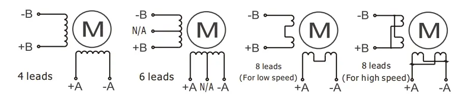
|
| +B, -B |
Dimensions
Frequently Asked Questions (FAQ)
What is the default microstep configuration for the YKE2204M stepper drive?
The default microstep configuration is 1 (200 PU/Rev). To set the drive to this default mode, both the SW6 and SW5 switches must be set to the ON position.
How do I configure the drive for Half Current or Full Current operation?
Current mode is controlled via the SW4 switch. Setting SW4 to the OFF position configures the drive for Half Current, while setting SW4 to the ON position configures it for Full Current.
What power supply specifications are required for the YKE2204M?
The driver requires a DC input voltage range of DC18-36V and a power supply with a power output rating of greater than 100W.
Do I need external resistors for the control signal inputs?
Yes, if the control signal voltage exceeds 5V. A current limiting resistor must be added: use an 820Ω resistor for 12V control signals, and a 2KΩ resistor for 24V control signals.
What do the PWR and ALARM indicators signify?
The green PWR LED lights up when power is properly supplied to the drive. The red ALARM LED lights up to signal faults such as over-current, under-voltage, or over-voltage conditions.
How does the MF (Motor Free) signal work?
When the MF signal is activated (low level), the motor coil current is turned off, allowing the motor shaft to be rotated freely by hand without magnetic resistance.