


Hot Products
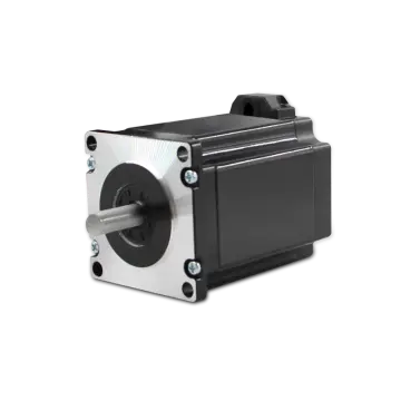
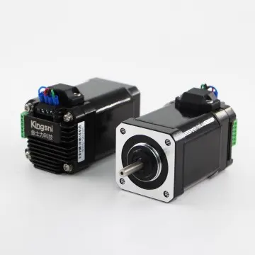
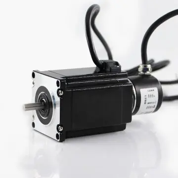


China Stepper Motor YKE2204M - High Precision & Reliable Performance from Trusted Suppliers and Factory
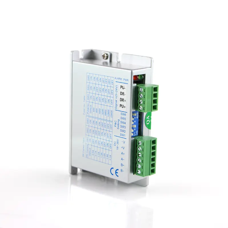
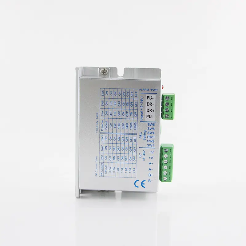
YKE2204M Microstep Setting
| Microstep | 1 | 8 | 16 | 32 |
|---|---|---|---|---|
| PU/Rev | Default (200) | 1600 | 3200 | 6400 |
| SW6 | ON | ON | OFF | OFF |
| SW5 | ON | OFF | ON | OFF |
SW4: OFF = Half Current | ON = Full Current
YKE2204M Current Setting
| Current RMS | Default (0.2) | 0.4 | 0.5 | 0.7 | 0.9 | 1.1 | 1.4 | 1.6 |
|---|---|---|---|---|---|---|---|---|
| Current Peak | Default (0.3) | 0.5 | 0.7 | 1.0 | 1.3 | 1.6 | 1.9 | 2.2 |
| SW3 | ON | ON | ON | ON | OFF | OFF | OFF | OFF |
| SW2 | ON | ON | OFF | OFF | ON | ON | OFF | OFF |
| SW1 | ON | OFF | ON | OFF | ON | OFF | ON | OFF |
Terminal Introduction
| Symbol | Function | Specification |
|---|---|---|
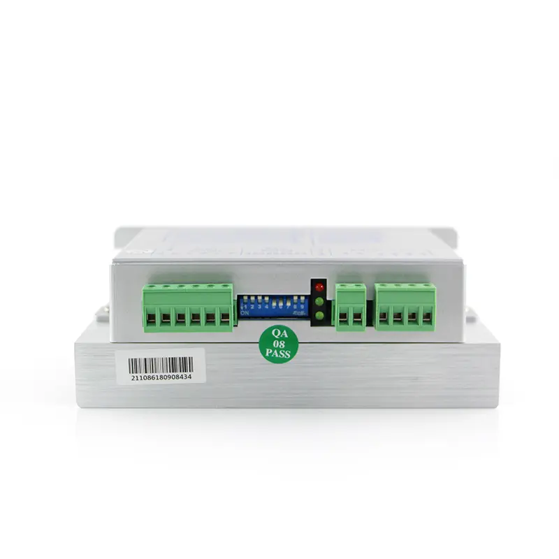
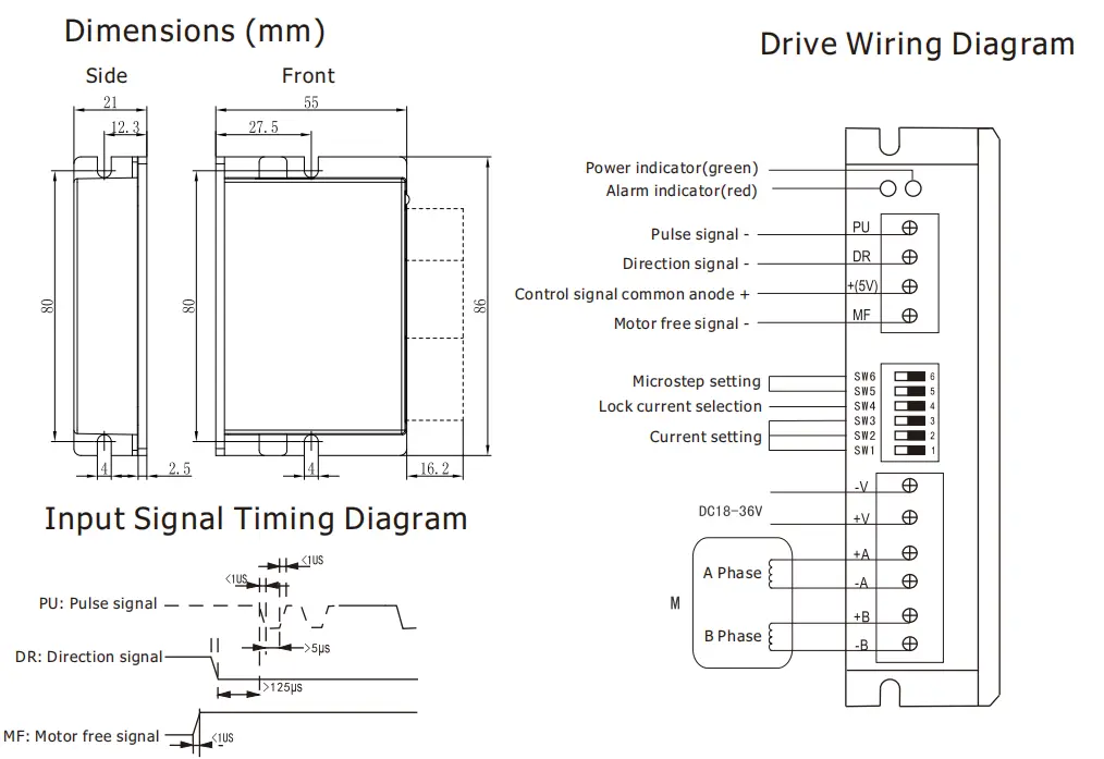
| PWR | Power indicator | When power on, the green indicator lights up. |
| ALARM | Fault indicator | When over current, under voltage or over voltage, the red indicator lights up. |
| PU | Pulse signal (photoelectric isolation -) | Effects on falling edge, the motor moves a step when the pulse goes from high to low. Built-in input resistance 384Ω, requirements: low level 0-0.5V, high level is the same as common anode, pulse width >5us |
| DR | Direction signal (photoelectric isolation -) | Used to change motor direction. Built-in input resistance 384Ω, requirements: low level 0-0.5V, high level is the same as common anode, pulse width >5us |
| +(5V) | Control signal (common anode +) | 3.3V-24V can drive, the current limiting resistor must be added when voltage > 5V. Need to connect with resistor of 2KΩ when voltage is 24V, and connect with 820Ω when it's 12V. |
| MF | Motor free signal (optical isolation -) | When effective (low level), the motor coil current is turned off and the motor is free. Built-in input resistance 384Ω, requirements: low level 0-0.5V, high level is the same as common anode, pulse width >5us |
| -V | Power supply - | DC18-36V, DC input, power supply > 100W |
| +V | Power supply + | |
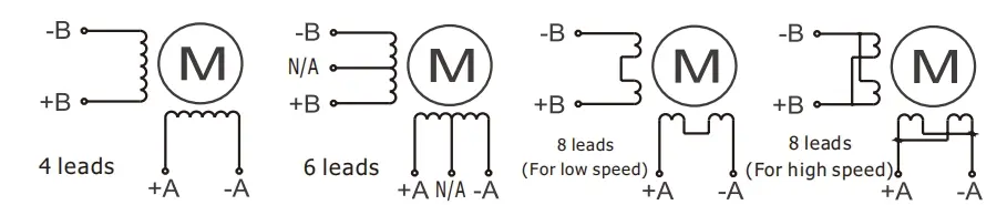
| +A, -A | Motor connection |
|
| +B, -B |
Dimensions
Frequently Asked Questions (FAQ)
1. How do I configure the microstep settings on the YKE2204M stepper drive?
Microstep settings are configured using the DIP switches SW5 and SW6. For example, to set the drive to 16 microsteps (3200 PU/Rev), switch SW6 to OFF and SW5 to ON. Refer to the Microstep Setting table for other combinations.
2. What is the difference between Half Current and Full Current modes?
This is controlled by switch SW4. Setting SW4 to OFF selects Half Current mode, which reduces motor heating when the motor is at standstill. Setting SW4 to ON configures the drive for Full Current mode to maintain maximum holding torque.
3. How do I choose the correct current settings for my motor?
You can adjust the Current RMS and Current Peak settings using switches SW1, SW2, and SW3. Match these switch combinations with your motor's rated current specifications as shown in the YKE2204M Current Setting table.
4. What do the PWR and ALARM LED indicators represent?
The green PWR indicator lights up when the drive is powered on. The red ALARM indicator lights up to signal a fault condition, such as over-current, under-voltage, or over-voltage issues.
5. Do I need external resistors for the control signal inputs?
The control signals support 3.3V to 24V. However, if the control signal voltage is greater than 5V, you must add a current-limiting resistor: connect a 2KΩ resistor for a 24V signal, or an 820Ω resistor for a 12V signal to protect the optocouplers.
6. What are the power supply requirements for the YKE2204M?
The drive requires a DC input voltage range of DC18-36V. The power supply should have a power rating greater than 100W to ensure stable operation of the stepper motor.