Leave Your Message

How to Repair a Stepper Motor

Stepper motors are found in 3D printers, CNC equipment, camera sliders, and many small automation systems. Their steady movement can conceal faults until a carriage skips, a shaft vibrates, or the motor only hums. Stepper Motor Repair starts with careful diagnosis, not immediate part replacement. Small clues matter.

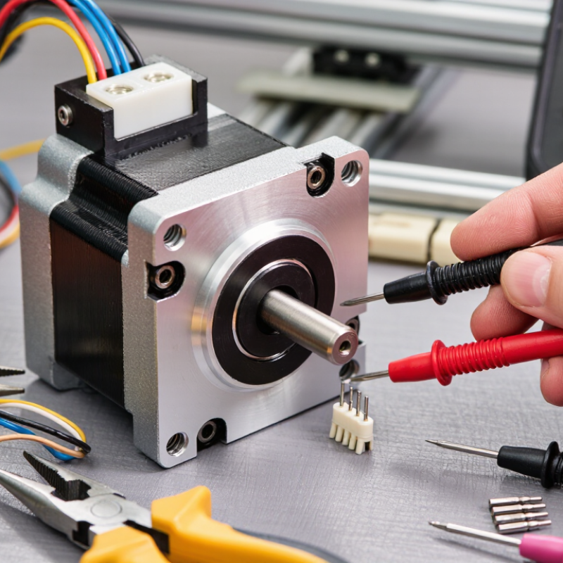
This guide explains how to inspect a motor, check its wiring and connections, and look for mechanical resistance before opening the housing. A multimeter can help identify winding problems, while a gentle hand test may reveal a binding shaft. Disconnect power before handling the motor, and avoid forcing the shaft or guessing at wire connections. Driver settings and damaged cables can mimic motor failure, so test the surrounding system too. That distinction is easy to miss.

Repair methods depend on the motor’s design and the damage. Loose connectors may be simple to fix; burnt windings or damaged bearings can make replacement more practical. Even experienced technicians can misread a symptom, especially when the motor works intermittently. A repair is not automatically the best repair. Ask whether the fault is truly inside the motor, and whether the result will be reliable under normal use. The sections ahead offer practical checks and cautious repair steps, while noting when a motor should be inspected by a qualified technician.

How to Repair a Stepper Motor

Identify the Motor and Record Its Rated Phase Current and Winding Resistance

Before repairing a stepper motor, identify its type and write down its rated phase current and winding resistance. Check the motor’s label, service sheet, or original machine documentation. Record the exact model and lead count; wire colors alone are not dependable. Take a clear photo before disconnecting anything.

Power must be off. Separate the motor leads from the driver, then use a multimeter to find winding pairs. On a four-wire motor, each pair should show a finite resistance; unrelated wires should read open. Motors with six or eight leads may have center taps or selectable winding connections, so map each lead carefully. Measure at room temperature and record the meter, lead configuration, and reading in ohms. Small errors happen.

Rated phase current is the current specified for one winding, not necessarily the power supply’s output current. Note the value and units exactly as printed. This matters when setting a compatible driver later. Resistance readings can reveal an open winding or a major mismatch between phases, but they do not prove the motor is healthy. I’ve seen tidy notes miss whether the reading included a center tap. Include that detail, even if it seems obvious.

Disconnect Power Before Testing the Motor or Driver

How to Repair a Stepper Motor

Disconnect Power Before Testing the Motor or Driver

Before checking a stepper motor, switch off and unplug its power supply. Never pull motor wires while the driver is energized; a brief disconnect can damage driver components. Wait for stored charge to dissipate, following the equipment manual. Then use a suitable meter to confirm that the circuit is no longer powered. If you are unsure how to verify this safely, stop and ask a qualified technician.

With power disconnected, inspect the motor leads, plugs, and terminals for loose connections, bent pins, or heat-darkened insulation. A connector may look seated but still have a weak contact. Check winding resistance only as directed by the motor or machine documentation, and compare readings between paired coils. An open or very different reading may indicate a damaged winding or cable. Do not assume the motor is faulty until you have checked the wiring. I’ve seen that assumption waste time.

Map Coil Pairs With a Multimeter and Compare Resistance With the Datasheet

Before opening the motor, disconnect it from the driver and power supply. A live circuit can distort readings and damage the meter. Label every lead, then set the multimeter to resistance. Touch the probes together and note their resistance; cheap leads may add a small amount.

For a four-wire stepper, test each lead against the others. A winding pair usually gives a finite, stable reading, while unrelated leads show open circuit. Mark the two pairs before reconnecting anything. On six-wire motors, center taps complicate the pattern: a center tap often measures about half the resistance to either end. Check the wiring diagram if the readings do not fit. Don’t guess.

Compare each winding’s resistance with the datasheet, using the same measurement points. The two phases should usually be close to each other. A large difference, an open reading, or a value far below specification can indicate a damaged winding or internal connection. Account for probe resistance and temperature; copper resistance changes as the motor warms. I find probe contact is easy to overlook. A loose touch can make a healthy coil look faulty, so repeat the measurement with steady pressure. Resistance alone cannot confirm every fault, but it narrows the search before you inspect connectors or test insulation.

Inspect Bearings, Shaft, and Rotor; Check NEMA 17’s Nominal 42 mm Face

Before opening a stepper motor, disconnect it from the driver and power supply. Turn the shaft gently by hand. A magnetic, notched feel is normal; grinding, scraping, or uneven resistance is not. Check for dust, metal flakes, and heat discoloration near the bearing seats. Small clues matter.

Look for shaft wobble by rotating it slowly and watching the tip against a fixed reference. A bent shaft may cause vibration or uneven coupling wear. Check for side-to-side play, but do not mistake slight movement for a failed bearing without comparing it with the motor’s specifications. Bearings should turn smoothly, without gritty spots or excess noise. The rotor should not rub the stator. If inspection requires opening the housing, mark the end-cap orientation first; reassembly can shift alignment. This check is easy to rush, so repeat it before ordering parts.

For a NEMA 17 motor, the “17” refers to its nominal 42 mm square face, not its body length or shaft diameter. Measure across the mounting face, then check hole spacing and shaft dimensions separately. A mismatch can make a healthy motor seem faulty. Not proof. If the face measures near 42 mm but the motor still binds, inspect its mount for uneven pressure. I would not assume the frame size identifies every internal part; dimensions vary by model.

Stepper Motor Repair: Typical NEMA 17 Dimensions

A NEMA 17 motor commonly has a face near 42 mm, with a 31 mm mounting-hole spacing, a 22 mm pilot, and a 5 mm shaft. These are typical dimensions, not universal tolerances; check the motor’s drawing before repair. Inspect bearings for roughness or play, and check the shaft and rotor for damage or rubbing.

Reassemble and Set Driver Current to the Motor’s Rated Phase Current

After checking the windings and rotor, bring the stepper motor back together on a clean bench. Keep dust away from the air gap. Align the end plates gently, then tighten the screws in a cross pattern so the housing seats evenly. Do not force a plate that catches; a trapped wire or shifted bearing can cause binding. Turn the shaft by hand. The magnetic detents are normal, but scraping or a sudden tight spot deserves another look.

Before connecting power, confirm the motor’s rated phase current from its reliable technical documentation. Set the driver’s current limit to that value, not to the motor’s supply current. A driver may specify settings as peak or RMS current, and the difference matters. Check its instructions and use the matching figure. This part is easy to rush. I have seen a motor run briefly at an incorrect setting, only to become too hot to touch.

Power down before changing wiring or driver settings. After setting the limit, secure the connections and apply power with the motor unloaded. Let it hold for a short period, then check for unusual heat, vibration, or odor. A warm case can be normal; rapid heating is not. If the driver’s adjustment method is unclear, pause and verify it rather than guessing. The rated phase current is a ceiling, not a reason to turn the setting higher for more torque.