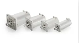
KSSM series radiation resistant servo motor
The KSSM series servo motor is a special servo motor designed for application environments such as ultra-high vacuum ultra-high tem- perature, deep low temperature, and irradiation. The shell is made of stain- less steel material and uses a rotary transformer as the motor position feedback component. Rated power of 400W, 750W.1800W, 3800W, volt- age level of 48VDC/220V AC/380VAC.
Choosing a stepper gear is not a matter of matching a motor shaft and hoping for the best. In a packaging line, a conveyor indexing load may need high reduction and low backlash. A compact pick-and-place axis may need quick response instead. The right choice depends on torque, speed, duty cycle, mounting space, and the precision the machine must hold.
Motion-control engineer Elena Park offers a useful rule: “Choose the gear ratio for the load’s real motion, not the catalog’s largest torque number.” That principle frames this guide to the 7 best Stepper Gears for industrial applications. A high ratio can increase output torque, but it may also reduce speed and add lost motion. Small details matter. Check shaft alignment, lubrication needs, operating temperature, and whether the gearhead can handle repeated starts and stops.
The options ahead cover common gear styles and practical selection trade-offs. Compare rated torque with peak loads, and check backlash against the accuracy your process requires. Consider the enclosure, too; dust and washdown can shorten service life when protection is overlooked. Datasheets do not always show how a unit behaves after months of cycling. That uncertainty deserves attention. These picks can narrow the field, but the final choice should reflect measured loads, the motor’s limits, and the machine’s actual operating conditions.
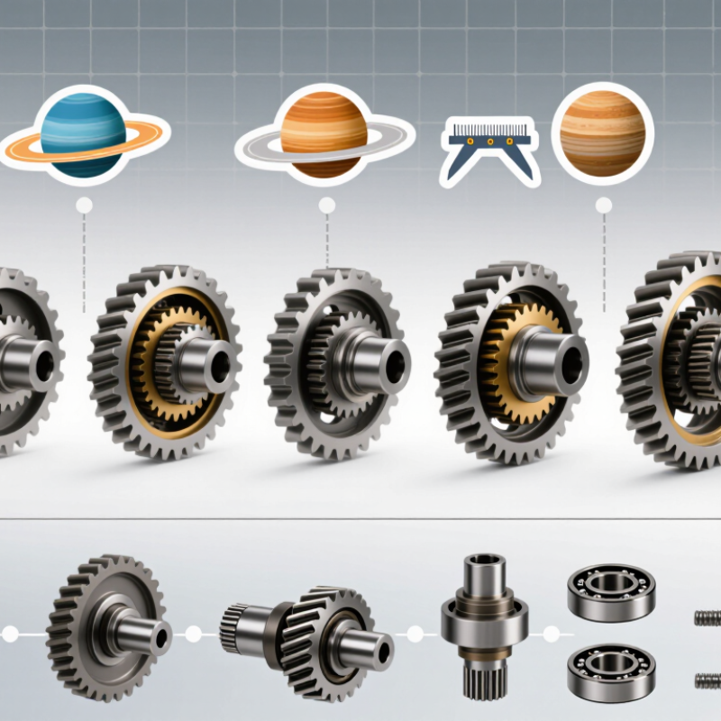
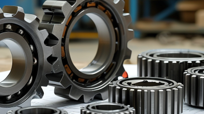
A stepper gear assembly connects a motor shaft to a driven machine through meshing gears, supported by bearings inside a rigid housing. The gear set may use spur, helical, or planetary arrangements. Each design balances space, noise, load capacity, and cost differently. The housing also helps keep lubricant around moving surfaces and limits contamination.
Its purpose is to trade speed for torque. A reduction ratio of 5:1, for example, can reduce output speed while increasing available torque, minus losses from friction and gear inefficiency. The motor advances in measured steps, and the gearbox scales that rotation at the output. Small errors matter. Backlash can create slight movement before the output responds, especially when direction changes. Gear teeth, shaft alignment, and bearing condition all influence repeatability.
For industrial use, selection should start with the required output speed, load, duty cycle, and positioning accuracy. A calculated torque rating is not automatically usable torque; starts, stops, temperature, and shock loads can change the result. Heat tells a story. If a gearbox runs unusually hot or sounds rough, check lubrication, alignment, and loading before increasing motor current. Even a well-sized assembly may need adjustment after installation, because real mounting surfaces are rarely perfect.
| Gear Type | Basic Structure | Operating Principle | Typical Industrial Uses | Key Advantages | Selection Considerations | Indicative Reduction Range |
|---|---|---|---|---|---|---|
| Planetary Gearhead | A central sun gear drives several planet gears inside an internally toothed ring gear. A carrier supports the planets and commonly serves as the output. | Multiple gear meshes share the load. The output carrier rotates more slowly than the input, increasing available output torque while reducing speed. | Robotics, packaging machinery, indexing tables, automated assembly, and compact positioning axes. | High torque capacity for its size, coaxial input and output, and good load distribution. | Check backlash, rated output torque, duty cycle, lubrication, and permitted radial and axial loads. | Often about 3:1 to 100:1 across one or more stages; available ratios depend on the design. |
| Spur Gearhead | Parallel shafts are connected by straight-toothed cylindrical gears. | Teeth engage directly to transmit rotation between parallel shafts. A compound train or additional stages increase the reduction. | Conveyors, feeders, small machine tools, and cost-sensitive, moderate-speed positioning systems. | Simple construction, high mechanical efficiency, and straightforward maintenance. | Tooth engagement can create noise and vibration. Consider backlash, lubrication, and the load capacity of each stage. | Commonly about 2:1 to 10:1 per stage; compound gear trains can provide higher overall reductions. |
| Helical Gearhead | Cylindrical gears have angled teeth and are arranged on parallel or, in some designs, crossed shafts. | Angled teeth engage progressively rather than all at once, transmitting motion smoothly between shafts. | Continuous-duty conveyors, automated production lines, and machinery where smooth, relatively quiet operation is useful. | Smoother and often quieter engagement than straight-toothed spur gears; suitable for sustained loads. | Angled teeth produce axial thrust, so bearings must support it. Efficiency and heat depend on the gearbox design. | Often about 3:1 to 10:1 per stage, with higher reductions possible in multistage units. |
| Worm Gearhead | A screw-like worm meshes with a toothed worm wheel, usually on perpendicular shafts. | Rotation of the worm advances the wheel tooth by tooth, producing a large speed reduction in a compact arrangement. | Compact right-angle drives, rotary positioning, gates, and equipment that benefits from a high reduction in one stage. | Can provide high reduction in a small package and changes the direction of the drive by 90 degrees. | Sliding contact can generate heat and reduce efficiency. Do not assume the gearbox is self-locking; verify this for the specific design and load. | Commonly about 5:1 to 100:1 in a single stage, depending on geometry and product design. |
| Bevel Gearhead | Conical gears transmit motion between intersecting shafts, often at a right angle. | Meshing bevel teeth redirect rotation from one shaft axis to another; additional stages can provide further reduction. | Right-angle machine drives, compact automation layouts, and equipment with intersecting shaft arrangements. | Changes drive direction efficiently and can fit applications where a parallel-shaft gearbox is unsuitable. | Confirm shaft angle, mounting arrangement, backlash, bearing capacity, and whether the required reduction needs multiple stages. | Often about 1:1 to 5:1 per stage; actual ranges vary by bevel gear arrangement. |
| Strain-Wave Gearhead | A thin flexible spline, a rigid circular spline, and an elliptical wave generator form the core assembly. | The wave generator flexes the spline so its teeth engage the circular spline at two opposing regions. The tooth-count difference produces a large reduction. | Robotic joints, precision positioning axes, compact rotary tables, and applications requiring low backlash. | High reduction in a compact unit and very low backlash in suitably designed gearheads. | Check allowable torque, torsional stiffness, shock-load limits, life under cyclic flexing, and the gearbox’s specified backlash. | Commonly about 30:1 to 160:1 in a single stage, depending on tooth counts and design. |
| Cycloidal Gearhead | An eccentric input drives a cycloidal disc whose lobes interact with pins or rollers in a surrounding housing; output pins transfer motion from the disc. | The eccentric causes the disc to orbit and rotate slowly relative to the housing, creating a large reduction through the difference between the disc lobes and housing pins. | Heavy-duty positioning, indexing equipment, industrial robots, and drives exposed to shock or fluctuating loads. | Compact high reduction, multiple contact points, and strong resistance to shock loads in appropriately rated designs. | Evaluate backlash, vibration, output-bearing loads, speed limits, and the manufacturer’s duty-cycle and lubrication requirements. | Often about 10:1 to 100:1 in a stage; specific constructions may differ. |

Selection note: Reduction ranges are indicative, not guaranteed specifications. A gearbox increases torque by reducing speed, but actual output torque is limited by motor capability, gearbox efficiency, thermal limits, and rated mechanical loads. Match the gearhead to the stepper motor’s torque-speed curve, required positioning accuracy, duty cycle, and load inertia.
Selecting gears for an industrial stepper motor starts with the load, not the catalog. Estimate the required output torque, including startup peaks and friction from the driven mechanism. Then check the gear ratio against the motor’s usable speed range; more reduction can increase torque but may slow the machine. A conveyor moving heavy parts needs different gearing from a small indexing table. Measure the actual load if possible. Calculations alone can miss binding or uneven friction.
Backlash matters when the motor must position parts repeatedly. A few degrees of lost motion may be acceptable for a mixer, but not for a pick-and-place axis. Compare the gear’s rated torque with the application’s duty cycle, not just its peak rating. Continuous operation creates heat. Check the specified service life, lubrication needs, and allowable operating temperature, too. A neat datasheet can still mislead. Verify the limits with the supplier’s test conditions.
Mounting details deserve attention before purchase. Confirm shaft diameter, keyway or coupling style, available space, and alignment tolerances. In dusty or damp areas, inspect the enclosure rating and sealing method. These details are easy to overlook. A gear that fits on paper may need a custom adapter in the workshop. That adds cost and can introduce misalignment, so leave room for installation and maintenance access.
Industrial stepper applications use seven common gear types: spur, helical, planetary, worm, bevel, harmonic, and cycloidal.
Spur gears are simple and efficient, making them suitable for light loads and straightforward positioning.
Helical gears engage gradually and often run more quietly, though their angled teeth create axial forces that bearings must handle.
Planetary gearboxes pack high reduction into a compact housing, useful when a machine needs torque without a large footprint.
Check the rated input speed and backlash, not just the advertised ratio.
Worm gears can provide substantial reduction in a small space. Their sliding contact may generate heat, so duty cycle and lubrication matter.
Bevel gears redirect motion between intersecting shafts, such as in an angled conveyor drive.
Harmonic drives offer compact, high-ratio motion with low backlash, but their flexibility and load limits need careful review.
Cycloidal reducers tolerate shock loads well in some designs, though size and noise vary.
A neat chart can still mislead.
Match the gear type to the stepper’s torque curve, operating speed, load inertia, and positioning accuracy. For example, a vertical axis may need a brake; a gearbox alone should not be assumed to hold every load safely.
Test under real duty conditions. Small differences matter. Gearbox efficiency, backlash, temperature rise, and mounting alignment can change results.
Selection may take iteration, especially when the machine’s load is inconsistent.
Choosing a gear for a stepper motor starts with the load, required motion, and working environment.
Spur gears suit simple, cost-conscious drives with parallel shafts, though they can be noisy at higher speeds.
Helical gears run more smoothly under steady loads, but their thrust forces need proper bearing support.
Planetary gears offer compact torque multiplication and often fit machines with limited space.
For slow, heavy loads, a worm gear can provide substantial reduction in a compact arrangement. Its efficiency and heat buildup deserve careful checking during long duty cycles.
Bevel gears redirect motion between intersecting shafts, useful when a conveyor or indexing table needs a right-angle drive.
Harmonic gears provide high reduction with little backlash, but their flexing elements may not suit every impact-heavy application.
Cycloidal gears handle shock loads well, though vibration and size can complicate integration.
Match the gear to the actual motion profile, not just peak torque. A vertical axis holding a platform needs different checks from a belt moving small parts back and forth.
Include acceleration, starts per minute, lubrication, temperature, and expected service life in the selection. Also check reflected inertia: a ratio that raises output torque can make the motor slower to respond.
The neat calculation may still miss a real load change. A prototype run under working conditions can reveal that.
A stepper gear is only as useful as its match to the load. Spur gears are straightforward and often economical, while helical gears can run more smoothly but create axial forces. Planetary designs offer compact reduction, though their service needs may be less simple. Check output torque, speed, allowable backlash, and duty cycle together. A high reduction ratio can improve positioning, but it also lowers output speed and adds losses. Small details matter.
During installation, keep the motor shaft and gear input aligned. Even slight misalignment can increase bearing loads, noise, and wear. Use the specified fastener torque, and avoid forcing a coupling onto the shaft. Check lubrication requirements before startup; grease-filled units may not need frequent relubrication, while other designs do. Keep dust and metal chips away from exposed teeth. Clean work helps.
Maintenance should follow operating conditions, not just a calendar. Record temperature, vibration, and unusual sounds during normal production, then compare readings over time. A warm housing may be expected, but a sudden rise deserves investigation. Inspect for leakage, loose mounts, and changes in backlash. Gear ratings are useful, not guarantees: shock loads, frequent reversals, and poor alignment can shorten service life. Real installations are rarely perfect. Leave room for adjustment, and verify performance under the actual load before increasing cycle speed.
Typical gearbox efficiency ranges provide a starting point for comparing performance. Actual results depend on gear ratio, load, lubrication, alignment, and number of stages.
Installation and maintenance: Follow the gearbox maker’s alignment, lubrication, and load requirements. Check for excess heat, noise, vibration, and lubricant deterioration during routine inspections. Worm-gear efficiency varies substantially with design and ratio.