


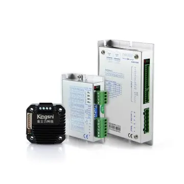


Stepper drive YKE2204M
Key Features
● 4 constant torque microstep setting, up to 32 microsteps
● Smooth and accurate current control, effectively reduce motor heating
● The highest pulse response frequency is 100KHz
● Excellent smoothness in low-speed and low frequency microsteps
● Optically isolated differential signal input, strong anti-interference ability
● Drive current is adjustable below 2.2A
● Voltage input range: DC18~36V
● With over voltage, under voltage etc. fault protection
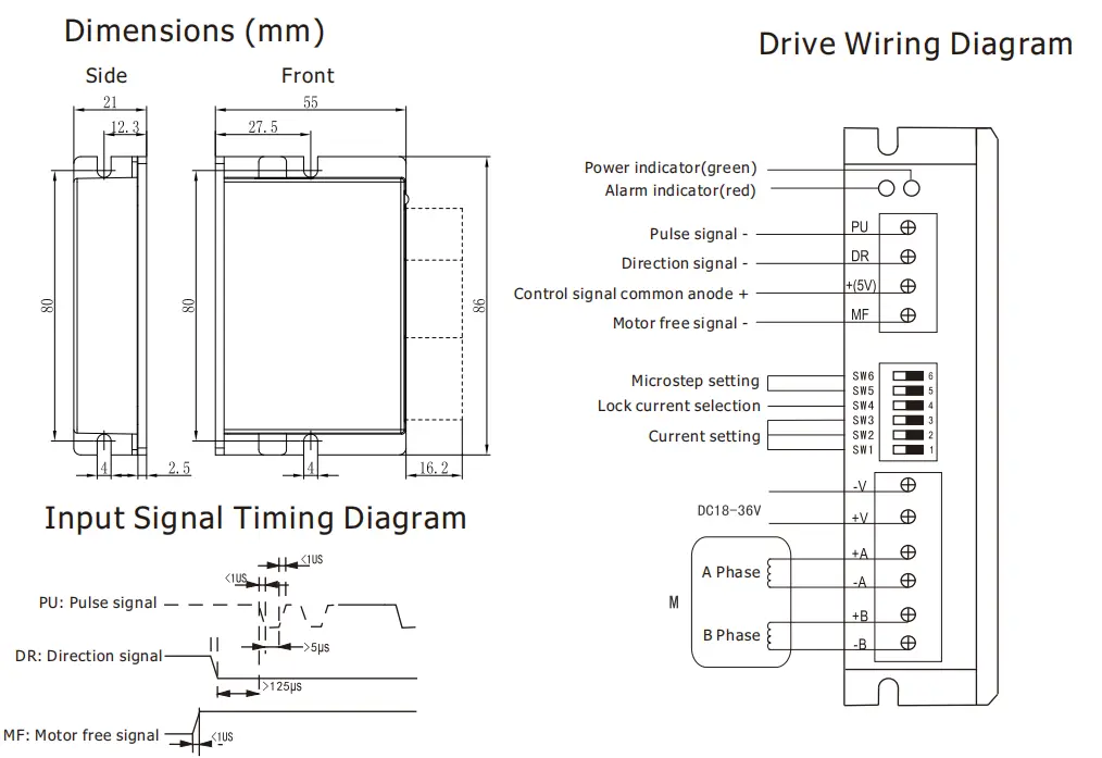
● Small size, volume 86*55*21 (mm³), weight 0.12kg
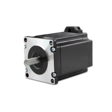
● Suitable for 42mm(NEMA17) 2 phase open-loop stepper motors

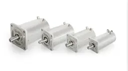
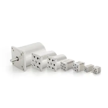
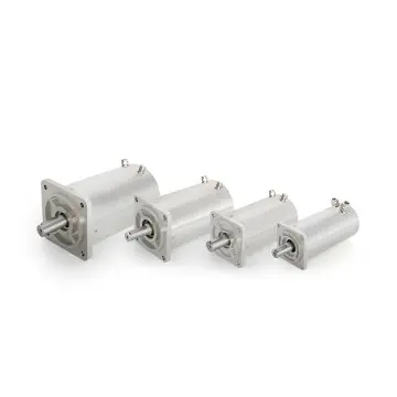
KH series stepper motors
28/42/57/86mm
48/51/56/58/60/65/76/80/84/118/156/165/201mm
D = single shaft
SZ = double shaft
Blank = without brake
B = with brake
Blank = without feedback
**IE = Incremental encoder
*** AE = Absolute encoder(RS485, Modbus RTU)
Blank = Without integrated mounted stepper drive
DRC = stepper driver mounted on the side of the motor
DRH = stepper driver mounted at the rear end of the motor
*It is not possible to install both brake and position feedback devices on one single motor.
**In order for the incremental encoder signal to be received and processed by the closed-loop stepper drive, the encoder output signals must be 5V differential signals with a maximum resolution of 2500PPR.
*** The absolute encoder feedback signals need to be received and processed by the user′s controller.
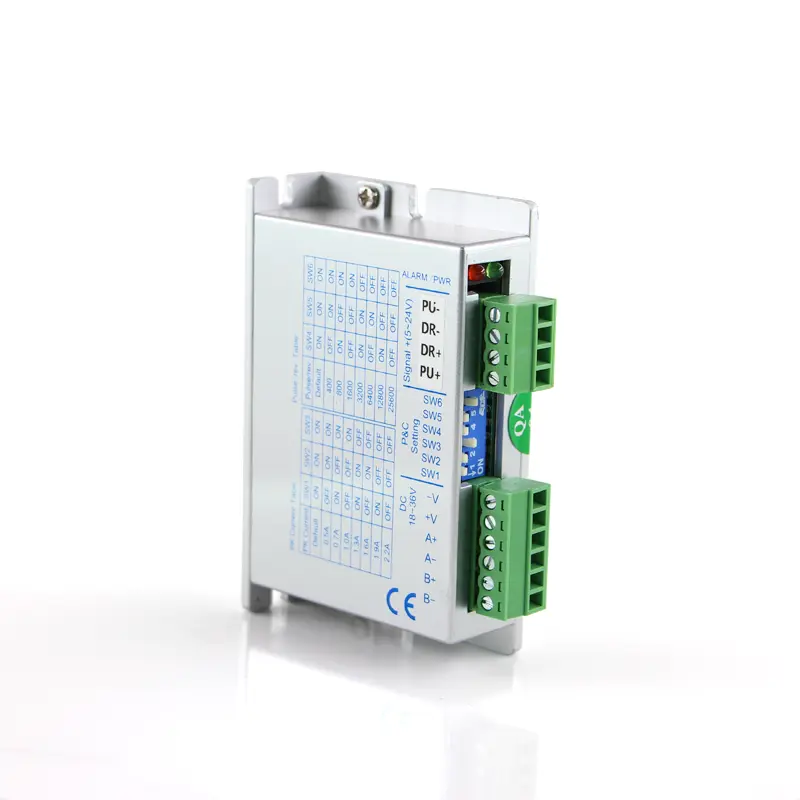
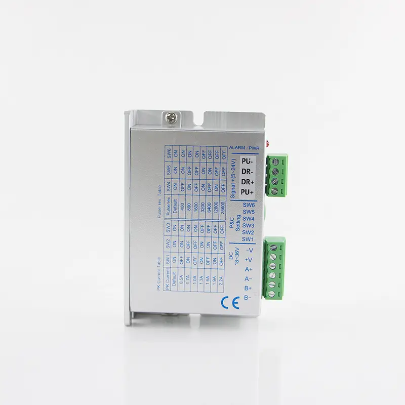
YKE2204M Microstep Setting
|
Microstep
|
1 | 8 | 16 | 32 |
|
PU/Rev
|
Default(200) | 1600 | 3200 | 6400 |
| SW6 | ON | ON | OFF | OFF |
| SW5 | ON | OFF | ON | OFF |
YKE2204MCurrent Setting
|
Current RMS
|
Default(0.2) | 0.4 | 0.5 | 0.7 | 0.9 | 1.1 | 1.4 | 1.6 |
|
Current Peak
|
Default(0.3) | 0.5 | 0.7 | 1.0 | 1.3 | 1.6 | 1.9 | 2.2 |
| SW3 | ON | ON | ON | ON | OFF | OFF | OFF | OFF |
| SW2 | ON | ON | OFF | OFF | ON | ON | OFF | OFF |
| SW1 | ON | OFF | ON | OFF | ON | OFF | ON | OFF |
TerminalIntroduction
|
Symbol
|
Function
|
Specification
|
| PWR |
Power indicator
|
When power on, the green indicator lights up.
|
| ALARM |
Fault indicator
|
When over current, under voltage or over voltage, the red indicator lights up.
|
| PU |
Pulse signal
photoelectric isolation -
|
Effects on falling edge, the motor moves a step when the pulse goes from
high to low. Built-in input resistance 384Ω, requirements: low level 0-0.5V,
high level is the same as common anode, pulse width >5us
|
| DR |
Direction signal
photoelectric isolation -
|
Used to change motor direction. Built-in input res is tance 384Ω,requirements: low level 0-0.5V, high level is the same as common anode,pulse width >5us
|
| +(5V) |
Control signal
common anode +
|
3.3V-24V can drive, the current limiting resistor must be added when voltage>5V. Need to connect with resistor of 2KΩ when voltage is 24V, and connect with 820Ω when it's 12V
|
| MF |
Motor free signal
optical isolation -
|
When effective (low level), the motor coil current is turned off and the
motor is free. Built-in input resistance 384Ω, requirements: low level 0-
0.5V, high level is the same as common anode, pulse width >5us
|
| -V |
Power supply -
|
DC18-36V, DC input, power supply>100W
|
| +V |
Power supply +
|
|
| +A,-A |
Motor connection
|
 |
| +B,-B |
Dimensions