


Servo motor considerations and troubleshooting
1. Low Acceleration Settings in High-Tech Drives Leading to J1 Alarm
When the acceleration settings within a High-Tech drive are set too low, while the PLC issues pulses with a higher acceleration rate, it can result in excessive positional deviation in the servo motor. Consequently, the Servo drive triggers a J1 position error overlimit alarm. This discrepancy arises because the drive cannot keep pace with the rapid changes in commanded motion, leading to a significant error accumulation.
2. Grounding Issue Causing Circuit Breaker Tripping
A grounding issue between the High-Tech drive and the servo motor can cause the circuit breaker to trip. To resolve this, ensure that the drive's grounding terminal is reliably connected to the earth. Proper grounding minimizes electrical noise and ensures safety by providing a path for fault currents to flow.
3. Profinet I/O Communication Between Third-Party Servo Drives and Siemens PLCs
Servo drives from different manufacturers, such as ABB's E180 and E190 series, support communication with Siemens PLCs via Profinet I/O. These drives come standard with single-axis motion control capabilities and support various communication protocols including EtherCAT, PowerLINK, Profinet I/O, Modbus TCP, and Ethernet IP. However, it's worth noting that only Siemens servo drives' Profinet offers full-mode control features like multi-axis synchronization and interpolation. Third-party drives, including ABB's, support Profinet I/O, which limits their functionality with Siemens PLCs to non-synchronized and non-interpolated operations.
4. PLC Output Signal Requirements for High-Tech Servo Drives
High-Tech servo drives require PLC pulse and direction signals in NPN configuration. PLCs from brands like Delta, Panasonic, and Mitsubishi typically provide NPN outputs, which are compatible with High-Tech drives without additional hardware. Conversely, Siemens PLCs generally output signals in PNP configuration, necessitating a PNP-to-NPN signal conversion module for compatibility with High-Tech drives.
5. PLC Output Signal Requirements for Copley Servo Drives
In contrast to High-Tech drives, Copley servo drives require PLC pulse and direction signals in PNP configuration. Siemens PLCs, which natively output PNP signals, are directly compatible with Copley drives. However, PLCs from Japanese manufacturers like Delta, Panasonic, and Mitsubishi, which output NPN signals, require a signal conversion module to convert NPN to PNP for compatibility with Copley drives.
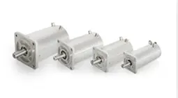
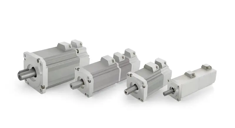
6. Control Precision of KECM Servo Motors
The control precision of KECM servo motors, when driven by High-Tech drives, is influenced by various factors such as servo gain adjustment, mechanical system stiffness, and the manufacturing accuracy of the motor and encoder. With a resolver feedback system counting 65,536 positions per revolution, and 17-bit absolute encoders providing 131,072 counts per revolution, the actual control precision of these motors can exceed 10 arc-minutes.
7. Power Supply Compatibility for 48VDC Servo Motors
Servo motors rated for 48VDC can operate on a 24VDC power supply, albeit with reduced performance. Specifically, the motor's speed will be approximately 50% of its rated value. However, if the drive's output current meets the motor's rated current, the motor's torque output will not diminish. Alternatively, a DC/DC converter can be used to step up the 24VDC to 48VDC.
8. Maximum Distance Between Servo Motor and Drive
The maximum recommended distance between a servo motor and its drive is typically 20 meters, with no intermediate connections. If a longer cable run is necessary, it's crucial to implement shielding and anti-interference measures such as isolation transformers for the drive's main power input, proper grounding, and ferrite beads on power cables. If intermediate connections are unavoidable, ensure that the shielding of feedback cables is handled correctly to prevent electromagnetic interference.
In conclusion, the performance and reliability of servo motor systems hinge on meticulous configuration, compatibility checks, and adherence to technical specifications. By addressing common issues and understanding the signal and power requirements of various components, users can optimize their automation systems for maximum efficiency and accuracy.
